Wireless Charging Detector
I dropped my cell phone and cracked the screen, so I got a Google Pixel 6 and a wireless charging stand. I ended up looking up the “Qi” standard for these chargers. It seemed like the coils used to transfer energy weren’t particularly exotic in size, shape, material or manufacture, so I decided to try to receive some energy from the charging stand.
I’ve since revised this contraption.
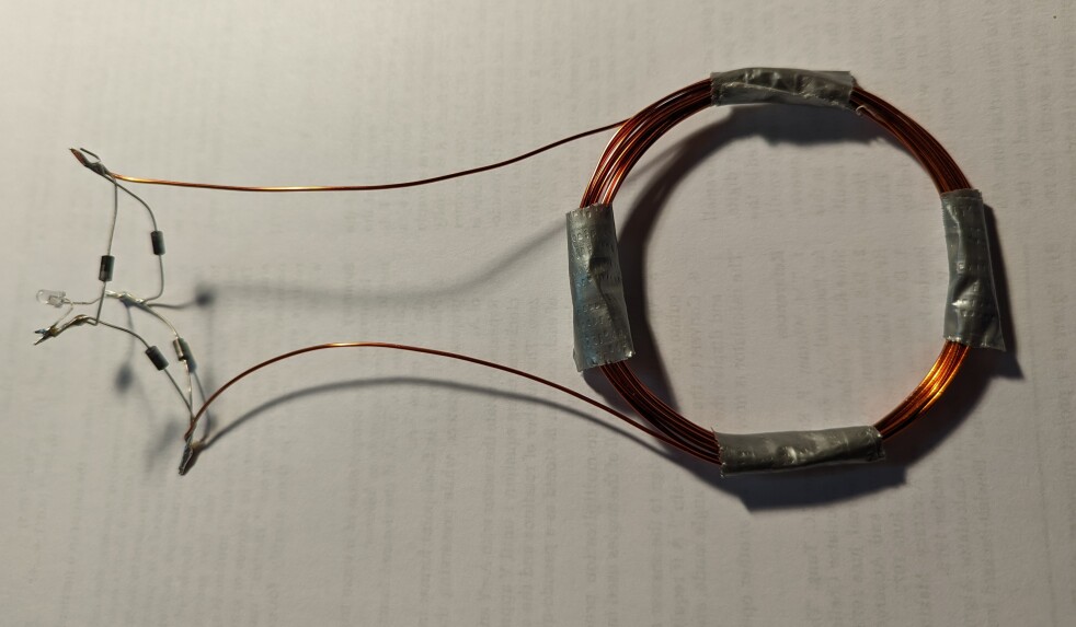
I piously believe I have some knowledge of electronics, so I decided to make a coil, put that coil close to the charging stand, rectify whatever voltage the charger’s pulses induce in the coil, and use that electricity to light an LED.
This contraption actually worked:

I did apparently burn out the first LED I put on it. The coil can actually receive quit a bit of energy.
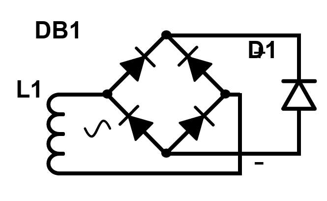
Here’s a schematic diagram of the circuit:

Bear in mind that I have no electronics training or education. I’ve put together a few kits and fiddled with circuits on breadboards. I may have made mistakes in all of this.
The diodes in DB1 are 1N4001 “switching diodes”. Apparently these are not recommended for new designs, but I used them because I got a pack of assorted diodes from Amazon, and they were in that assortment.
LED D1 is a generic blue LED, from a package labeled “C/V: 20mA 3-3.2V”
Coil L1 is 20 gauge enameled copper wire wrapped around a salsa jar 10 times. It was a little tricky to get the coil off the jar. The coil has a 2.75 inch inside diameter. I used 4 pieces of duct tape to keep it tidy. I have a suspicion that the coil size might matter, and that 2.75 inch diameter is a little big.
As far as I know there’s no part that’s hard to find, or magical in materials or construction.
It’s easy to ruin the LED if the coil gets too close to the wireless charging stand. If you build a similar device, move the coil up to the charging stand slowly. It puts out pulses of energy about every second or so. I can keep my coil about a pencil-diameter away from the charger and see pulses of light from the LED.
After figuring out that I’d ruined the first LED I’d soldered on my device, I put an analog voltmeter across the diode bridge. I was able to see the voltmeter’s needle jump with a very regular frequency. Later, I soldered another LED across the diode bridge.
Electronoobs youtube channel briefly shows something similar, but they put capacitors across the LED, and didn’t rectify the voltage from the charger’s pulses.
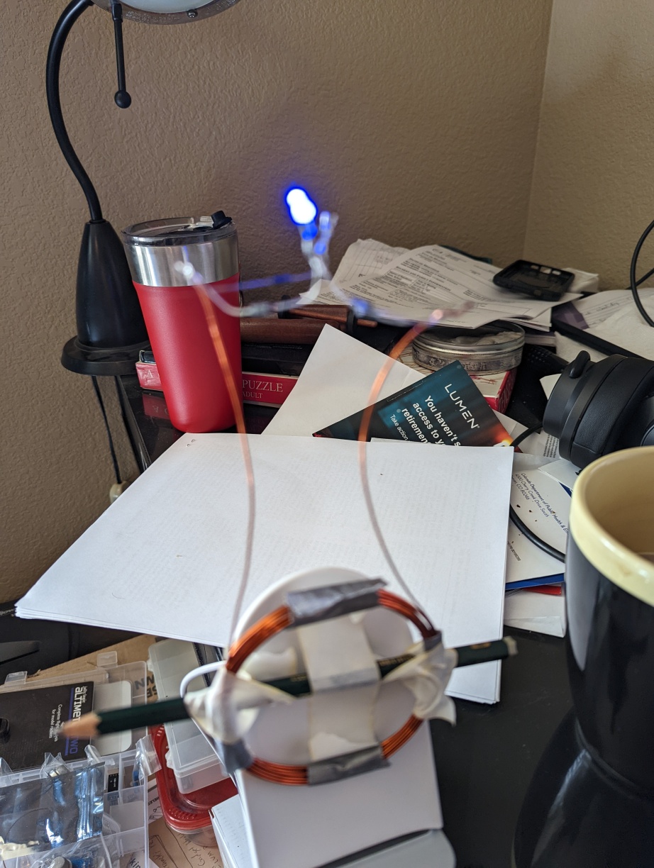
I taped the contraption to my charging stand. I got a picture of it in action:

In the image, the bottom of the coil is touching the stand, the middle of the coil is one pencil diameter off the stand. The top of the coil is about an inch away from the stand: the coil is slanted relative to the front of the charger. With the coil in the right spot, the LED flashes 3 beats out of 4, where 4 beats is just about a second. If I position the coil a little off, I only get 1 LED flash per second. I suppose if I read the Qi standard closely, I could figure this out.
