2 Transistor LED Flasher
In an attempt to gain some electronics knowledge, I bought $30 worth of components and breadboards from Amazon, and built a 2-transistor LED flasher.

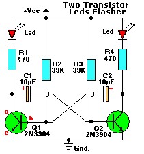
Here’s the schematic I used for the above contraption:

There’s tons of similar schematics and various instructions floating around. The schematic above lists “39K” resistors for R2 and R3. My cheap component set had 47KΩ resistors, but not 39K, so I used 47K. Worked just fine. I’d hazard a guess that about the only important things are using general purpose NPN transistors, and getting the transistor and LED pin out correct.
How does the RC time constant compare with the frequency of flashing?
τ = RC = (47 KΩ)(10 μf) = (47,000)(10*10-6) = 0.47 seconds
I timed 20 green LED flashes 5 times with my smartphone stopwatch app. I recorded a total of 54.5 seconds. There’s 19 intervals in each 20-flash timing period, so 95 intervals. That’s 54.5/95 = 0.57 seconds per interval. Each interval has 2 charge-discharge cycles, since the red LED flashes between green LED flashes. 0.57 seconds/2 = 0.29 seconds. That’s close to the 0.47 second RC constant.
If I change out the 10μf capacitors for larger, 22μf capacitors, τ = RC = (47 KΩ)(22 μf) = (47,000)(22*10-6) = 1.03 seconds
I time 3 sets of 10 green LED flashes, with substantially more consistent timings than the 20 green LED flashes. I measured a mean of 11.7 seconds per set of 10 flashes. There are 9 intervals in a 10-flash timing, so 11.7 seconds/9 = 1.3 seconds per interval. Each interval has 2 charge-discharge cycles, 1 for the red LED, one for the green, 1.3 seconds/2 = 0.67 seconds. That, too is close to the 1.03 second RC constant. Also, since I’ve got 2.2 times more capacitance, 0.29*2.2 = 0.64, that’s pretty close to 0.67
I conclude that RC constants do exist.
